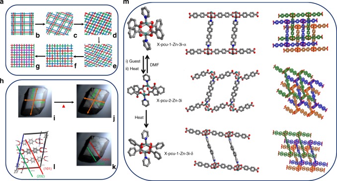
Fig. 4.
Structural transformation. a Proposed mechanism37 for conversion of X-pcu-1-Zn-3i-α to X-pcu-1-Zn-4i: b 3-fold interpenetrated pcu nets are offset; c structure in between α- and β-phase with networks tilted but still offset; d centered interpenetration of networks; e distortion leads to breakage of metal carboxylate and metal nitrogen coordination bonds; f non-coordinated carboxylate or nitrogen moieties bind to available metal centres; g 4-fold interpenetrated network.The interpenetrated networks are coloured green, red, blue and purple. h Thermal microscopy images: i as-synthesised crystal of X-pcu-1-Zn-3i-α; j X-pcu-1-Zn-3i-α after desolvation at 100 °C for 30 min; k and l cracks along (101) and parallel to (101) that occur as X-pcu-1-Zn-3i-α transforms to X-pcu-1-Zn-4i. m isomerisation of the node from square paddlewheel geometry (X-pcu-1-Zn-3i-α) to distorted tetrahedral geometry (X-pcu-2-Zn-3i) and then back to square paddlewheel (X-pcu-1-Zn-3i-δ). Three-fold Interpenetrated networks are presented in green, blue and yellow. Colour scheme: C, grey; O, oxygen; N, blue; Zn, dark green.

