
Fig. 2.
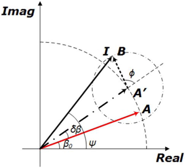
Phasor depiction of the proposed model. The original signal is denoted by A with a phase angle of β0. A is first rotated by δβ due to the presence of the timing jitter and the scanning variability. The resultant A′ is then added by an AWGN B with a random phase angle ϕ and being detected as I. The phase angle of the measured I is ψ.