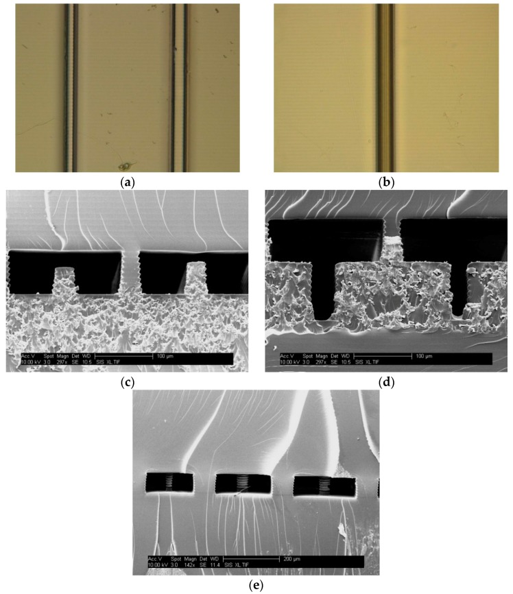
Figure 2.
Images of 3D printed features. (a) Top view photograph of 1500 ms exposure ridges designed 3 and 4 pixels (23 and 30 µm) wide. The ridges measured 25 ± 1 and 29 ± 1 µm; (b) Top view photograph of a 500 ms exposure (without compensation) trench designed 4 pixels (30 µm) wide, which measures 21 ± 0.5 µm; (c) SEM images of 1000 ms exposure interior ridges designed 5 and 6 layers tall. The ridges measured 46 ± 1 and 55 ± 1 µm tall, respectively; a support pillar is in the middle of the image; (d) SEM image of interior trenches at 1000 ms exposure without compensation designed 5 and 6 pixels (38 and 46 µm) wide, which measured 22 ± 0.7 and 34 ± 2 µm wide; (e) SEM image of interior pillar structures at 1500 ms exposure designed to be 5–7 pixels (38–53 µm) in diameter.

