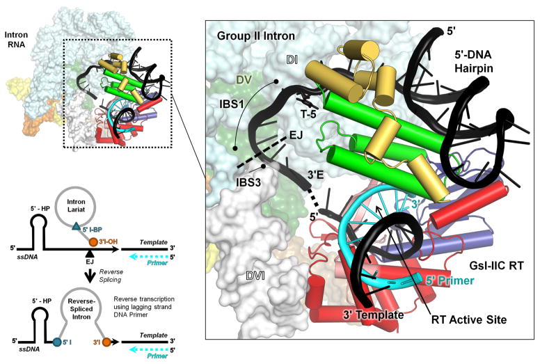
Fig. 10.
Model of the interaction of a GsI-IIC RNP with a DNA target site containing a 5′-exon hairpin just prior to the reverse splicing step of retrohoming. The complete model of the intron RNP is shown to the left, with the GsI-IIC RT binding region magnified in the box to the right. The position of T-5 is indicated. The model was derived from that in Stamos et al. [31] with the 5′-exon sequence of GsI-IIC34 replacing a generic hairpin. The intron model was constructed from the O. iheyensis intron lariat structure (pdb 5J02), with ligated exon DNA modeled based on an RNA bound to EBS1 and EBS3 in pdb 3IGI. The GsI-IIC RT containing a template-primer duplex (pdb 6AR1) was docked onto the intron RNA using positioning information from both the Ll.LtrB group IIA intron RNP (pdb 5G2X) and spliceosomal Prp8 (pdb 5GAN) cryo-EM structures. The hairpin was docked into the GsI-IIC RT structure using the 5′ exon from the Ll.LtrB RNP cryo-EM structure as a guide. EJ indicates the 5′-exon/3′-exon junction. Black cartoon: model DNA target site with 5′-exon DNA hairpin with the dashed line indicating the gap between the ligated exon DNA model and the RT-bound template strand; T-5 shown in stick figure. Cyan cartoon: primer; space-filling model: O. iheyensis intron; cylindrical cartoon: GsI-IIC RT, red: RT group II intron-specific inserts; salmon: RT fingers; blue: RT palm; green: RT thumb; yellow: RT D domain. The schematic at the bottom left shows the intron configuration before and after the reverse splicing step of retrohoming

