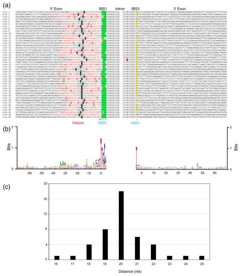
Fig. 3.
GsI-IIC insertion sites in the G. stearothemophilus strain 10 gene. (a) Sequence alignments comparing the 45 GsI-IIC insertion sites. Red letters indicate nucleotides that potentially base pair to form a 5′-exon DNA hairpin structure upstream of the intron-insertion site. Green highlighting indicates nucleotides in IBS1 than can base pair with EBS1 in the intron RNA, and yellow highlighting indicates the C or T residues at the IBS3 position that can base pair with the G at EBS3 in the intron RNA. A red highlight indicates mutation of the branch-point A residue of GsI-IIC21. The short vertical lines in the alignment indicate the exon-intron boundary. The intron EBS1 and EBS3 motifs are shown at the bottom in blue and the two nucleotides downstream of EBS1, which are conserved in all 45 copies of the intron, are shown in black. A black square indicates the center of the hairpin’s loop; for loops with odd numbers of nucleotides the 5′ half of the loop contains the additional nucleotide. (b) WebLogo showing sequence conservation in the 5′ and 3′ exons generated using WebLogo3 with standard parameters [63]. (c) Distance of the intron-insertion site from the top of the 5′-exon DNA hairpin. The variable distance between the top of hairpin loop (black) and intron-insertion site can also be seen in (a).

