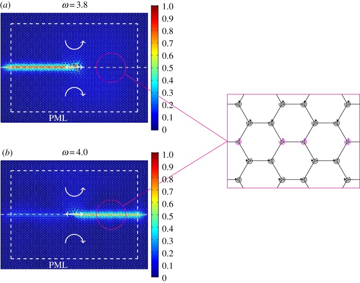
Figure 4.
Relative displacement amplitude fields in the chiral lattice at different frequencies of the applied time-harmonic displacement and for different spin directions of the spinners (indicated by the white circular arrows) above and below the interface. The time-harmonic displacement (represented by a straight white arrow) is applied to the central node of the lattice. In these computations, the absolute value of the spinner constant is |α| = 0.9, and the frequency of the applied displacement is (a) ω = 3.8 and (b) ω = 4.0 (see also figure 2f ). PML are attached to the sides of the model, as indicated by the dashed white lines. The interfaces between regions where spinners rotate in opposite directions are represented by dashed grey lines. To the right, we provide a magnification of the interface, where the spinners on the interface are shown in a different colour. The diagrams represent the ratios of the displacement amplitudes to the amplitude of the imposed displacement. (Online version in colour.)

