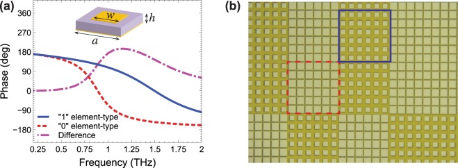
Figure 2.
(a) Numerically computed reflection-coefficient phase as a function of frequency, pertaining to the “1” (blue-solid curve) and “0” (red-dashed curve) element types, assuming normally incident plane-wave illumination with electric field parallel to the patch side. Also shown (magenta-dashed-dotted curve) is the phase difference between the two configurations (which becomes 180° at the design frequency of 1 THz). An infinite periodic structure is assumed, composed of unit cells (see inset) of period a = 50 μm, with patch sidelength w1 = 30 μm and w0 = 45 μm, for the “1” and “0” element-types, respectively; a substrate of thickness h = 20 μm is assumed, with εr = 3, , and perfectly electric conducting metallization. (b) Detailed view of an optical microscope image of a fabricated sample, with the 6 × 6 supercells pertaining to the “1” and “0” element-types identified with blue-solid and red-dashed squares, respectively.

