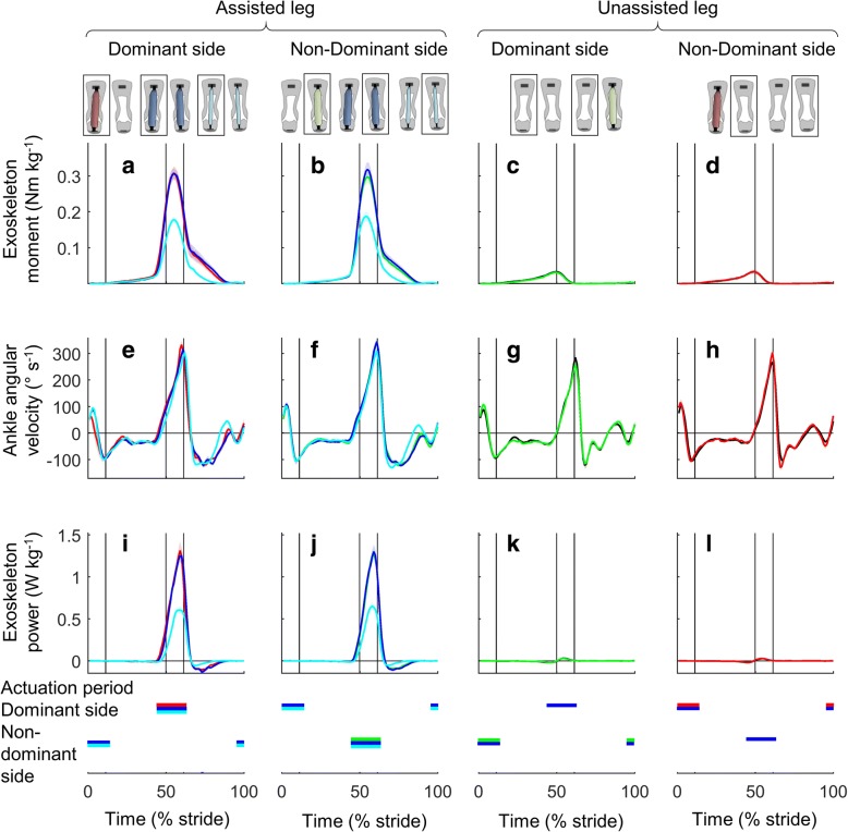
Fig. 3.
Actuation conditions. a-d Exoskeleton moment. e-h Ankle angular velocity. i-l Exoskeleton power. Left two columns show assisted leg. Right two columns show unassisted leg. Colored lines represent the Unilateral, Bilateral and Powered-Off conditions marked by rectangles in figures on top of the chart columns. Shaded area represents the standard error. Vertical lines show beginning and ending of single and double stance phases. Horizontal colored bars indicate the actuation period in conditions with corresponding colors

