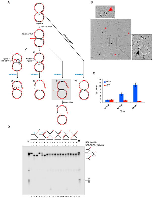
Figure 4. The Non-reversed Fork Abutting the ICL Is Subject to DNA Incisions.
(A) Model depicting three possible pathways of incision, after one fork has undergone reversal, and one pathway for breakage. The sigma structure expected if the non-reversed fork on the reversed intermediate undergoes incisions is highlighted in gray. See text for other details.
(B) EM image of pICL repair intermediates at 90 min in a mock-treated condition. Black arrowheads, sigma structures containing a reversed fork; red arrowheads, linear species. Similar results were seen in two other independent experiments.
(C) Quantification of linear structures during ICL repair in a mock-treated or p97i-treated reaction. Error bars indicate the range in two independent experiments. A time-dependent increase in linear species of similar magnitude was observed in two other experiments, but the data were not included in the quantification due to different time points or slightly different conditions.
(D) A series of 3′-radiolabeled (red asterisks) splayed arm and X-shaped substrates containing or lacking nascent strands (dotted arrows) were incubated with XPF-ERCC1 in the presence or absence of RPA for 60 min and the DNA analyzed by denaturing PAGE. M, radiolabeled marker oligonucleotides of indicated structures and sizes. Blue arrow, approximate position of incision. See Supplemental Experimental Procedures and Figure S3D for details of model substrate preparation.

