
Fig. 1. Overview of the dislocation manipulation.
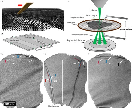
(A) Artistic representation of the manipulation process. Dislocations in bilayer graphene, which relax into atomic-scale topographic ripples, can be controlled using a fine tip mounted on a piezo-driven micromanipulator. (B) Overview of the types of dislocations to be considered for this work: In-plane dislocations are mobile contrary to the sessile out-of-plane dislocations. In-plane dislocations are of the partial type and necessitate a stacking fault between them. (C) Schematic representation of the in situ setup in the SEM. A low-energy electron probe is scanned over a graphene flake on a TEM grid. The transmitted electrons carrying the crystallographic information are detected with a segmented detector, allowing bright-field and different DF imaging modes (see fig. S2 for details on contrast formation). Micromanipulators can be placed below and above the sample to allow access from both sides for manipulations and mechanical cleaning. (D to F) Exemplary in situ dislocation manipulation process: Three dislocations are visible at the upper part of the hole in the support film. Dislocations 1 and 2 (as well as 3 and 2) enclose a different stacking order of AC stacking, compared to the AB stacking elsewhere. (E) Using a micromanipulator, the dislocations can be extended to about three times their length, in turn also changing their character from dominantly screw type to edge type and vice versa. The interaction of the dislocations also results in a dislocation reaction, creating an intersection that includes the energetically unfavorable AA stacking [see fig. S6 for high-resolution TEM (HRTEM) of such an intersection]. (F) Releasing the micromanipulator leads to an almost complete reversal of the dislocation structure due to line tension.