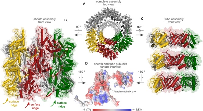
FIGURE 5.

Preliminary model of the extended sheath and tube assembly of R-type diffocin, generated on the basis of the sheath from R-type pyocin (PDB: 3J9Q; Ge et al., 2015) and the tube of phage φ812 tail (PDB: 5LI2, Nováček et al., 2016). A top view onto three disks of CD1363 sheath and CD1364 tube layers is given in (A) with the interacting subunits colored in yellow, red, and green, respectively. In (B), a side view of three disks of the CD1363 sheath assembly is shown. Because of helical disk stacking, the surface ridges wind around the particle. In (C), three disks of tube subunits are presented using the same color code as in (A,B). Of note, since the 5LI2 template for tube modeling contained a single tube disk only, generation of two additional disks for the R-type diffocin tube was performed via superimpositions on pyocin as described in the “Materials and Methods” section. White stars indicate positions of the attachment points for the loop comprising α-helix 1 in CD1364, which was excluded from the model due to clashes but might establish important inter-disk contacts to fill the gaps observed in the tube assembly. In (D), putative contact points between sheath and tube subunits of the R-type diffocin particle with the respective electrostatic potential are shown. For CD1363, the attachment helix α10 and for CD1364, the central β-barrel, is shown as cartoon.
