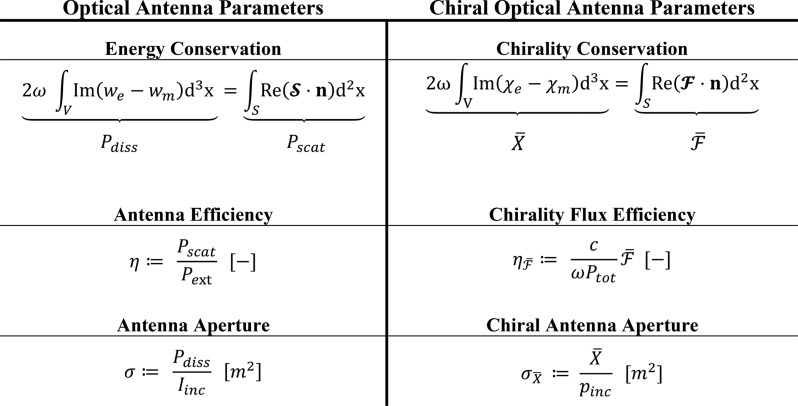
Table 1. Comparison of Optical Antenna Parameters (left) and Chiral Optical Antenna Parameters (right) Based on Their Governing Conservation Laws, Where ω is the Angular Frequency and n Is the Normal Vectora.
In the left column, we and wm are the complex harmonic
electric and magnetic energy densities,22 ,
,  is the
Poynting vector, Pdiss is the dissipated
power, Pscat is the scattered power, Pext = Pdiss + Pscat is
the extinction power, and Iinc is the
incident light intensity. In the right column, χe and χm are the complex harmonic electric and magnetic
optical chirality densities,22

 ,
,  is the
optical chirality flux, c is the speed of light, Ptot is the total power of the outgoing light,
and pinc is the incident power density.

