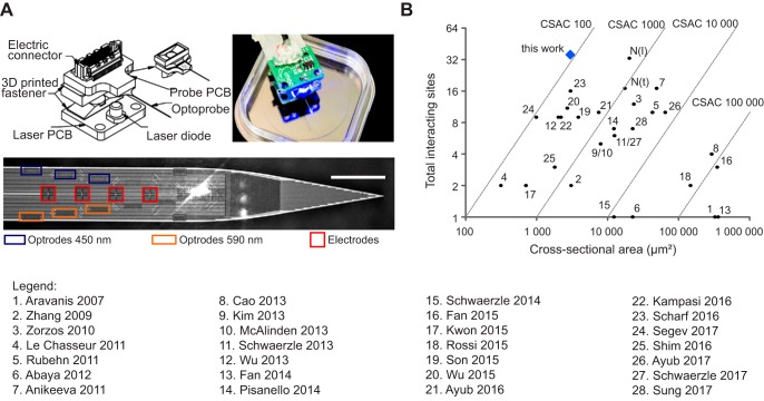
Fig. 1.
Optoelectrode with high density of interacting sites. A: schematic overview of probe. Top left, the optoprobe is glued on top of an electrical printed circuit board (PCB; probe PCB). A laser diode (LD) is soldered onto another PCB (laser PCB), which is joined to the probe PCB by a detachable thermal insulator. Top right, image of a fully assembled system. Bottom, close-up of the probe shank with the different optical outputs (470 nm, blue rectangles; 590 nm, orange rectangles) and electrodes (red squares). Each electrode is 10 × 10 µm; interelectrode distance is 1 µm. Scale bar, 100 µm. B: comparison of the density of interactive sites to existing neural interfaces, with numbers indicating their source (1, Aravanis et al. 2007; 2, Zhang et al. 2009; 3, Zorzos et al. 2010; 4, LeChasseur et al. 2011; 5, Rubehn et al. 2011; 6, Abaya et al. 2012; 7, Anikeeva et al. 2011; 8, Cao et al. 2013; 9,Kim et al. 2013; 10, McAlinden et al. 2013; 11, Schwaerzle et al. 2013; 12, Wu et al. 2013; 13, Fan et al. 2014; 14, Pisanello et al. 2014; 15, Schwaerzle et al. 2014; 16, Fan et al. 2015; 17, Kwon et al. 2015; 18, Rossi et al. 2015; 19, Son et al. 2015; 20, Wu et al. 2015; 21, Ayub et al. 2016; 22, Kampasi et al. 2016; 23, Scharf et al. 2016; 24, Segev et al. 2017; 25, Shim et al. 2016; 26, Ayub et al. 2017; 27, Schwaerzle et al. 2017; 28, Sung et al. 2017). N(l) and N(t) refer to a standard NeuroNexus probe with a linear or tetrode configuration, respectively. The total number of interacting sites was obtained by summation of all optical outlets and electrodes. The cross-sectional area is measured as the coronal section through the probe shank. The cross-sectional area coefficient (CSAC) is defined as the ratio of the cross-sectional area to the combined number of optical outlets and electrode sites.

