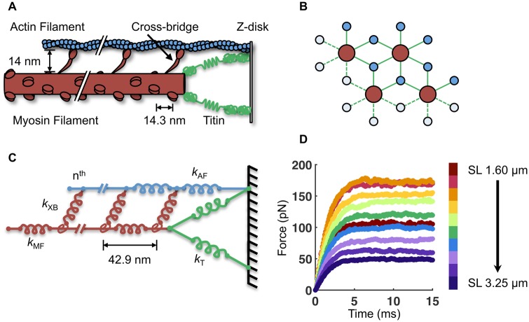
Fig. 1.
Description of the half-sarcomere model. A) A simplified schematic of the half-sarcomere, with the myosin filament in red, the actin filament in blue, and the I-band region of titin in green. B) The myosin and actin filaments are arranged in 3D with double-hexagonal symmetry. Four myosin and eight actin filaments are modeled with periodic boundary conditions to simulate a semi-infinite lattice. C) The half-sarcomere is modeled as an array of springs of different stiffness (k) for the myosin filament (MF), actin filament (AF), titin (T), and n cross-bridges (XB). Each myosin filament contains 60 crowns of three myosin motors (180 cross-bridges per myosin filament). D) By simulating 15 ms of isometric contraction, the steady-state force for each SL is measured. The average force of 50 independent runs with b = 7.5 μm−1 is shown here.

