
Fig. 3.
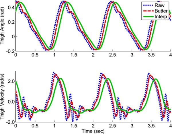
Top: the thigh angle (Raw) measured by the IMU (dotted blue line) compared against two filtered options: 1) a second order Butterworth (Butter) low-pass filter with a cutoff frequency of 5 Hz (dashed red line) and the Interpolating (Interp) filter method (solid green line). Bottom: the thigh velocity (numerically differentiated thigh angle) and the two filtered options. Signal disturbances from ground impact are observed in the thigh velocity (e.g., t ≈ 1.3 and 2.6 seconds). The Interpolating filter provides a more smooth signal than the Butterworth filter. Data is from 3 mph treadmill speed test.