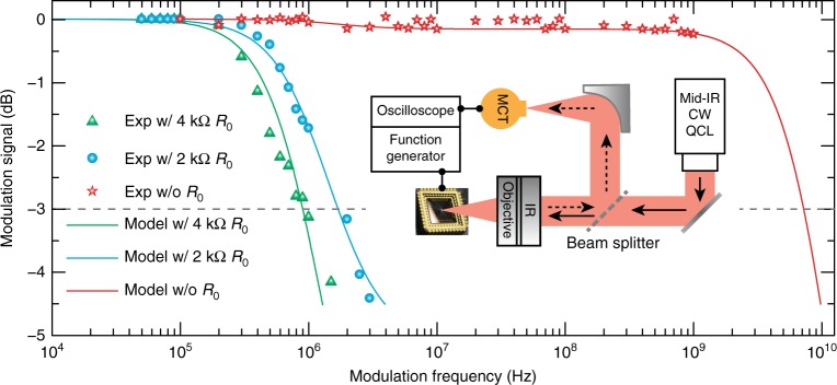
Fig. 4. Modulation speed of the hybrid graphene metasurface.
Symbols represent the measured modulation signal as a function of gate voltage frequency for the device with intrinsic modulation (red stars) and device loaded with an external resistor of R0 = 2 kΩ (cyan circles) or 4 kΩ (green triangles). The cyan and green curves represent the modulation fitting based on an equivalent circuit model when the metasurface modulator is loaded with R0 = 2 kΩ and 4 kΩ external resistors, respectively. The fitting parameters are then used to retrieve the intrinsic modulation characteristics of the metasurface modulator, represented by the red curve. Inset: schematic of the modulation speed measurement system

