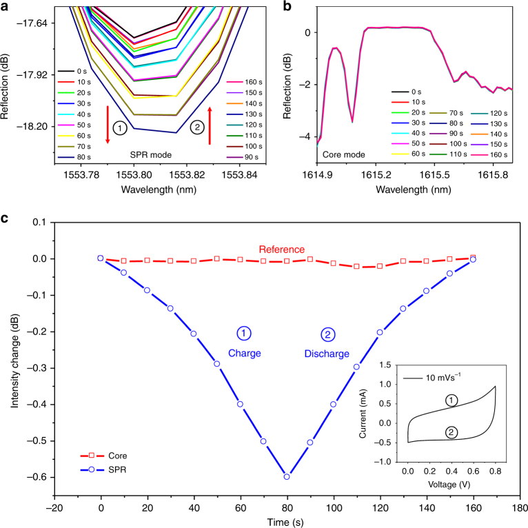
Fig. 2. Detailed charging and discharging of the supercapacitor from 0 to 0.8 V.
a Spectral response of the selected SPR resonance (the red arrow indicates the variation trend of the SPR spectral feature with time) and (b) unchanged core Bragg resonance. The electrochemical curve and the optical response are synchronously recorded. c Intensity change of the selected SPR resonance (blue dot) and the core Bragg resonance (red block) corresponding to one cycle of the CV curve of the supercapacitors at a scan rate of 10 mV s−1 (shown in the inset). The symbol ① represents the process of charging. Conversely, the symbol ② represents the process of discharging

