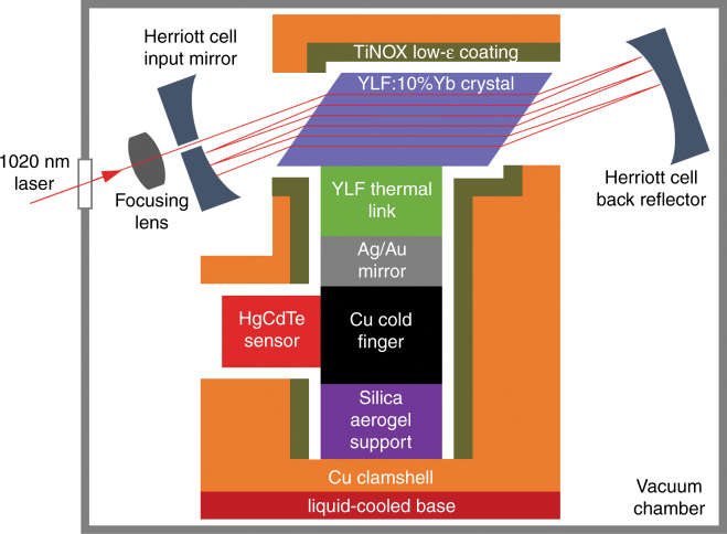
Fig. 1. Block diagram (not to scale) showing the components of the solid-state optical cryocooler.
The laser-cooling material (blue) is placed inside an astigmatic Herriott cell to enable multi-pass excitation by the pump laser. The sensor payload (red) is connected by a coldfinger (black), mirror (gray), and thermal link (green) to the laser-cooling material. A support element (purple) provides the mounting of this assembly within a closely fitting clamshell (orange), which is lined with a low-emissivity coating (olive) and mounted onto a liquid-cooled base (dark red). The cryocooler is contained within a vacuum chamber (gray)

