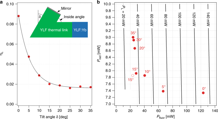
Fig. 4. Optimization of the YLF thermal link geometry.
a The fraction of fluorescence power reaching the link/mirror interface ηL for different tilt angles δ as obtained from a raytracing simulation (red circles) and a fit of the data to a single exponential function (black line). The inset shows a cross-sectional view of the kinked thermal link (green) attached to the YLF:Yb laser-cooling crystal (blue) and coated with a mirror on the interface that attaches to the coldfinger (see Fig. 1). The tilt angle δ is indicated. b Calculated heat load on the thermal link from thermal radiation Prad vs. the optical heat load due to fluorescence absorption at the link mirror Pfluor for links with different δ values. The calculation assumed link and clamshell temperatures of 135 and 300 K, respectively, Pin=47 W, ηcpl = 0.999, ηext = 0.996, and Rm = 0.97. Link geometries with an inside angle of (90o−δ) and 90o are shown as filled and open circles, respectively. Lines of constant total heat load PL = Pfluor + Prad are indicated

