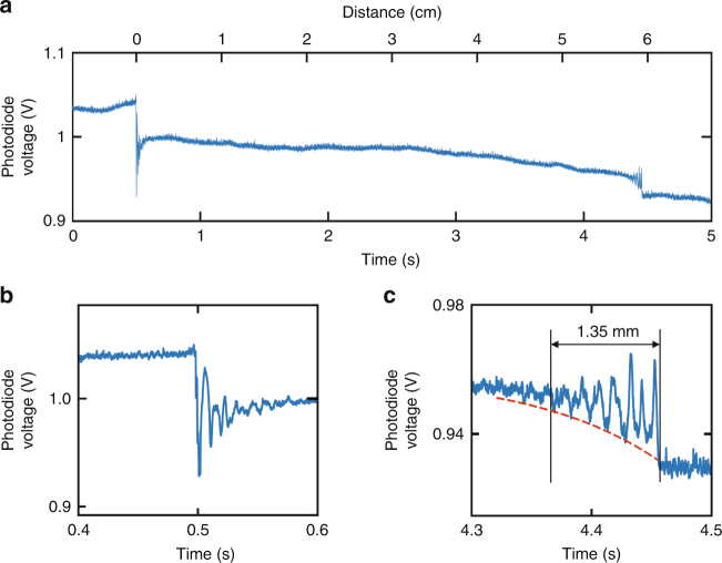
Fig. 2. Intermodal interference induced by trapped particles inside the HC-PCF.
a With one particle already loaded inside the HC-PCF, the temporal variation in transmitted power is measured as the second particle enters the fibre and approaches the first one. b Zoom into the time interval between 0.4 and 0.6 s, showing the fade-out of intermodal beating around the fibre endface. c Zoom into the time interval from 4.3 to 4.5 s, when the second particle approaches the first one. The red-dashed line is an exponential fit to the intermodal beating envelope

