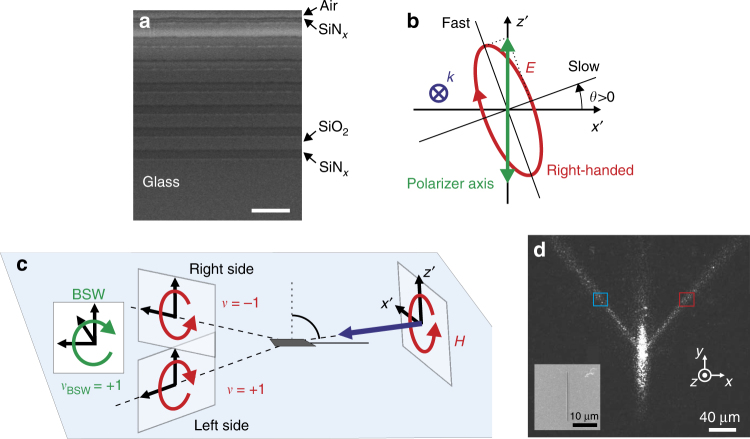
Fig. 3.
A simple all-dielectric platform unveiling the magnetic spin-orbit interaction. a SEM cross-section of the 1D photonic crystal (scale bar: 1 µm). b Schematic diagram of the elliptic polarization (electric optical field) generated by the polarizer (fixed) and the quarter-wave plate (rotating). c Schematic diagram of the magnetic field handedness in the helicity planes of the right and left BSWs for an incident right-handed polarization. The handedness is defined here by the parameter v: we have v = + 1 and v = − 1 for the clockwise and anticlockwise rotating magnetic fields, respectively. d Far-field optical image of the BSW obtained via excitation at λ = 1.55 µm of a 600 nm wide and deep groove. The groove is 20 μm long. The laser beam is incident from air onto the top surface of the 1D PC at almost the grazing angle (incidence angle: 80°, see Supplementary Fig. S2). This image originates from light scattering at the sample top surface. The incident light is linearly (TM) polarized here, to reveal the two symmetric BSW propagation directions provided by the phase-matching condition. Figure inset: SEM top view of the groove milled into the top surface of the 1D photonic crystal

