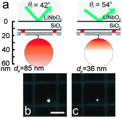
Figure 5.
(a) Schematic diagram of a 40-nm fluorescently labeled bead anchored to a TR-BSA-patterned supported bilayer by a biotin/NeutrAvidin linkage on a hybrid lithium niobate/SiO2 substrate. The vertical scale provides approximate distances for a 13-nm SiO2 layer. The shading further indicates the effects of excitation using TIRFM with two different angles of incidence. For simplicity, it does not reflect that only the outer 50% radius of the bead, corresponding to 80% of the volume, contains fluorescent dye, and it does not account for the collection factor discussed in the text. In the case on the left, the penetration depth is such that the excitation intensity covers the entire bead, whereas on the right, only a portion of the bead is excited. Corresponding TIRFM images of a 40-nm NeutrAvidin-coated bead anchored to a supported lipid bilayer containing 0.5 mol % biotin PE on a hybrid lithium niobate/SiO2 substrate for (b) θi = 42° (corresponding to dp = 85 nm), and (c) θi = 52° (corresponding to dp = 36 nm). The supported membrane was patterned by microcontact printing 3.5-μm wide grid lines of TR-BSA that are separated by 25 μm. (Bar = 20 μm.)

