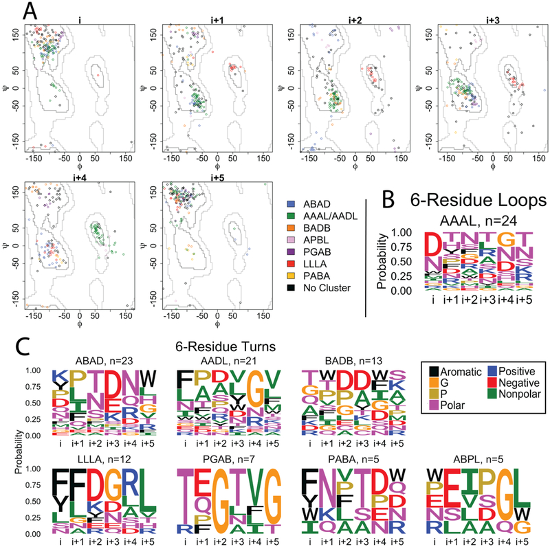
Figure 5. 6-residue strand connectors.
A) Clustering of the 6-residue loops and turns of OMBBs. Loops are shown with diamond markers; turns are represented by circle markers. Because the i+3 residue of the green cluster straddles the boundary between the D and A regions, the green cluster is labeled AAAL in the loops and AADL in the turns. B) Sequence logos for the 6-residue loops. C) Sequence logos for the 6-residue turns. Sequence logos are colored and grouped as in Figure 2.

