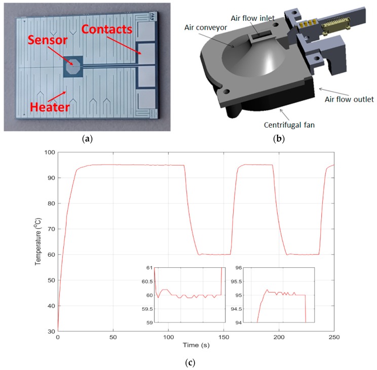
Figure 2.
(a) Flipside of the silicon chip: the heater is a printed serpentine occupying most of the area. The temperature sensor is in the center of the heated area; (b) Partial view of the mechanics underneath the cartridge holder. A curved, air conveying surface directs the aspirated hot air to the centrifugal fan underneath; (c) Example of thermal curve as obtained from the onboard chip sensor. The initial ramp is visible, followed by the earliest cycles—a long-denaturation protocol, with equal denaturation and annealing/extension times was set for clarity.

