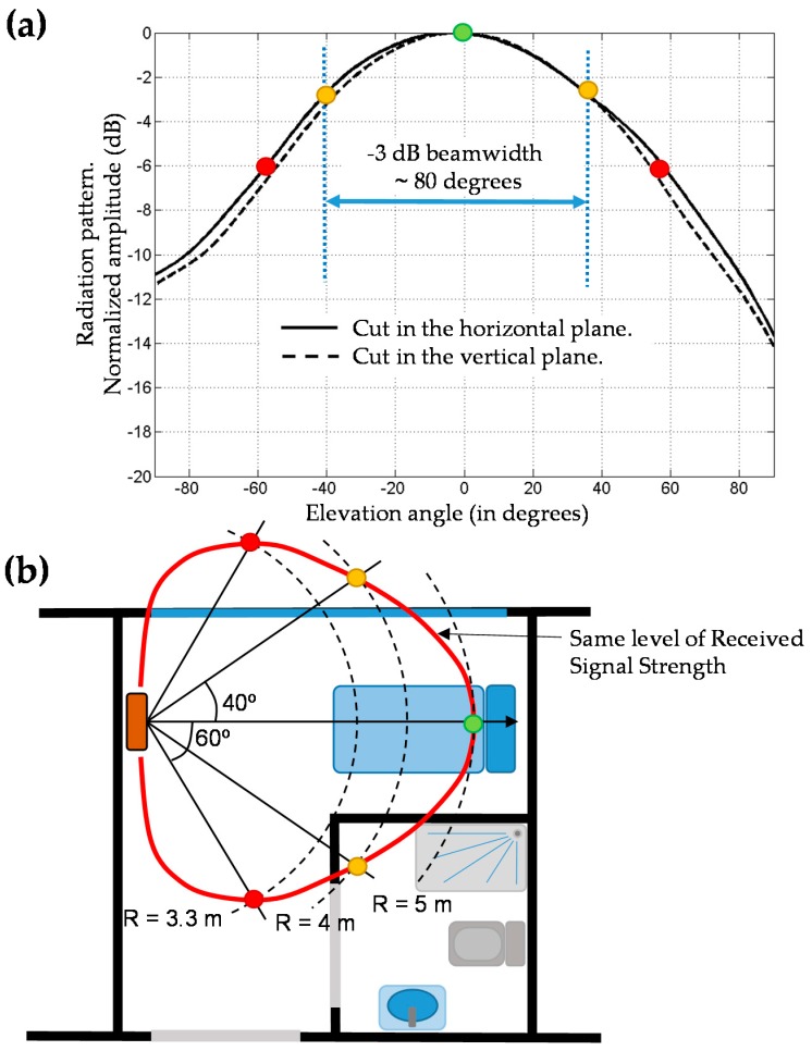
Figure 2.
(a) Radiation pattern of a directive UHF RFID. Main cuts are depicted, highlighting the −3 dB beamwidth. (b) Representation of the coverage area of the RFID antenna: red line represents all the points that receive the same signal strength taking into account indoor propagation model losses and the radiation pattern.

