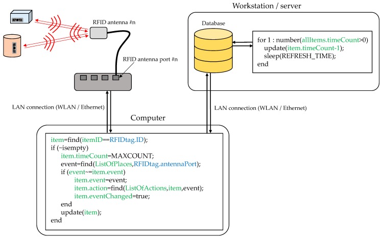
Figure 4.
Scheme of the connection between the RFID antenna, the RFID reader, the computer controlling the RFID reader, and the system database. Pseudo-code illustrating how the database is updated every time a RFID tag is read is outlined (information associated to the database is highlighted in green, while inputs from RFID reader are highlighted in blue).

