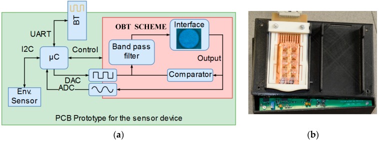
Figure 3.
(a) The block diagram for the implemented PCB (Printed Circuit Board) prototype of the sensor device. Interdevice communication is performed by data buses; Universal Asynchronous Receiver-Transmitter (UART) and Inter-Integrated Circuit (I2C). The microcontroller (µC) implements Digital to Analog (DAC) and Analog to Digital (ADC) converters to trigger/acquire the Oscillation Based Test (OBT) sensor signal. (b) A photo of the sensor device.

