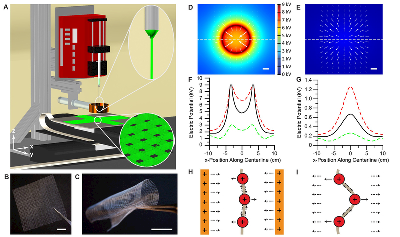
Figure 1. The 3D jet writing process yields precisely engineered fiber constructs.
(A) The 3D jet writing setup: An electrostatic lens effectively focuses the deposition of the fluid jet and computer directed stage movement allows for fibers to be organized into complex 3D patterns (bottom inset). (B-C) Examples of large-scale square patterned structures made by 3D jet writing. (D-E) Computer simulations of the electric potential in the x-y plane 3 cm below the tip of the orifice with (D) and without (E) a secondary electrode (acting as an electrostatic lens). The direction of the electric field at various points is indicated by white arrows. (F-G) Modeling of the electric potential along the x-axis marked by the dashed line in (D) and (E) illustrates the electric potential distribution both with (D) and without (E) a secondary electrode. Here red, black, and green lines represent a z-position 2, 3, and 4 cm below the capillary orifice, respectively. (H) The lens effect of the secondary electrode in (D) and (F) is demonstrated by the formation of an electric potential well, which drives the fiber towards the center of the secondary electrode. (I) In contrast, lack of a secondary electrode results in deflection of the fiber from the centerline which is the premise of the whipping instability. Scale bars represent 1 cm.

