Fig. 2.
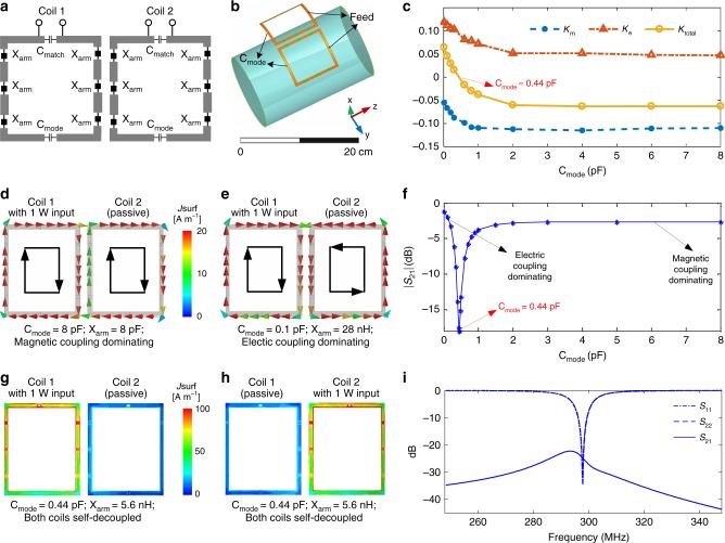
Self-decoupling a two-loop array. a Schematic of a pair of self-decoupled coils. b Electromagnetic simulation model of a pair of self-decoupled coils. The magnetic and electric coupling are balanced by tuning the Cmode capacitors, while adjusting the Xarm impedances to maintain coil tuning, and the Cmatch capacitors to maintain a coil input impedance of 50 Ohms. c Calculated magnetic and electric coupling coefficients (Km and Ke) versus Cmode. d Simulated vector current distributions of magnetic coupling-dominated coils. e Simulated vector current distributions of electric coupling-dominated coils. In both cases, Coil 1 is excited with 1 Watt and its current flows clockwise along its conductors. f The coils’ transmission coefficient (|S21|) versus Cmode. Coupling is minimized and the coils are self-decoupled for Cmode = 0.44 pF. g Simulated current distributions of the self-decoupled coils with Coil 1 excited. h Simulated current distributions of the self-decoupled coils with Coil 2 excited. In both cases, the residual currents due to coupling in the passive coils are negligible. i Simulated scattering parameters versus frequency for the self-decoupled coils

