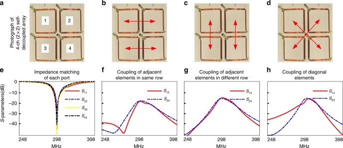
Fig. 8.
Self-decoupling of a multi-row array. a A constructed 2 × 2 self-decoupled array in which the coils’ feed ports are positioned at one corner and the Cmode capacitors are positioned at the opposite corner. Red arrows in b–d illustrated the three kinds of coupling of the 2 × 2 self-decoupled array. The Cmode values were chosen to balance decoupling between all elements, and were nearly the same. e–h Measured scattering parameter plots. The coupling between adjacent elements in the same row, adjacent elements in different rows, and diagonal elements were −17.5 dB, −15.2 dB and −15.4 dB, respectively

