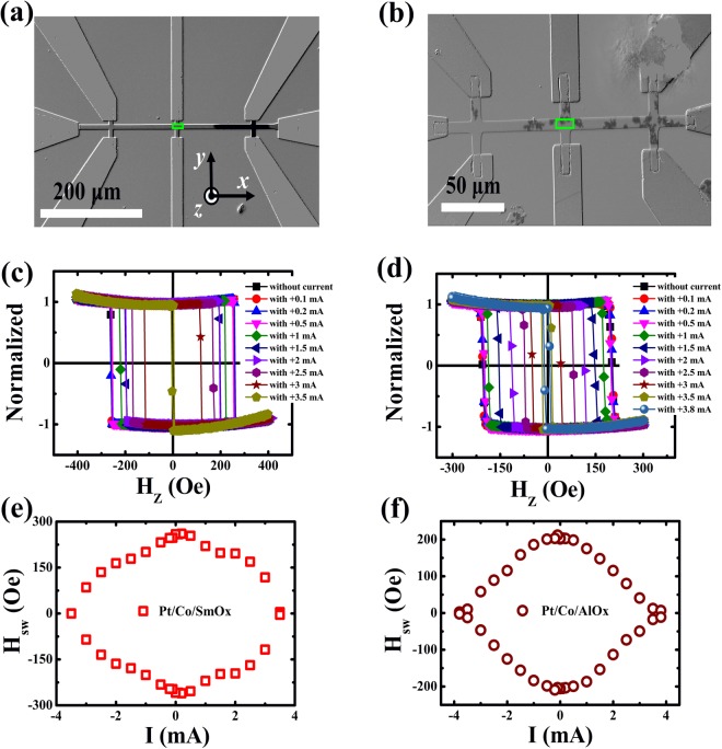
Figure 2.
Polar Kerr hysteresis loops at different direct currents. Representative Kerr images for Pt/Co/SmOx (a) and Pt/Co/AlOx (b) during the field-induced magnetization switching, showing the differences of the DW nucleation. The light (deep) color shows the “up” (“down”) domain or magnetized state. The green rectangles stand for the measured regions where polar Kerr hysteresis loops are collected. Polar Kerr hysteresis loops for Pt/Co/SmOx (c) and Pt/Co/AlOx (d) stacks at different direct currents. Switching phase diagram where Hsw varies against I for Pt/Co/SmOx (e) and Pt/Co/AlOx (f) stacks.

