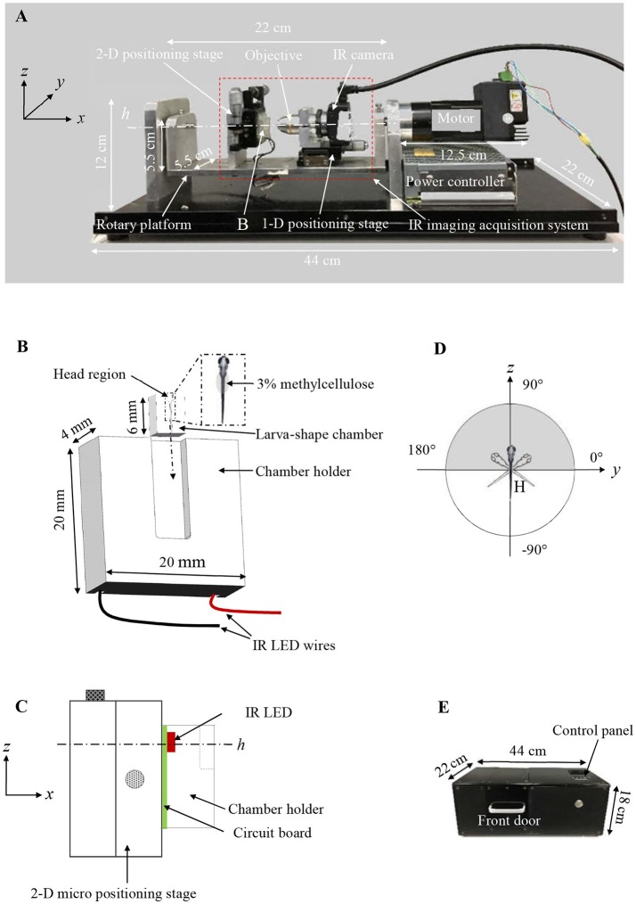
Figure 1.
(A) Customized VOR testing system. (B) A schematic drawing of the larva-shaped chamber and its holder. In the enlarged larva-shaped chamber (dashed rectangle), a larva is embedded in the chamber with 3% methylcellulose, dorsum is facing readers. After the larva-shaped chamber is inserted into its holder (following the dashed arrow), the chamber unit is in a position in which the larval head is up, perpendicular to the rotary platform swinging around the center (h) (C), allowing the larva to rotate or “tick-tock” about the earth horizontal axis within its frontal plane (the gray area in D). (C) A schematic drawing (in the yz plane) shows the assembly of the chamber holder (B), IR LED (red) & circuit board (green), the 2-D positioning stage for the y & z direction. (D) A schematic diagram shows the rotatory trajectory of the larva (head) (gray) and the platform (white). (E) The black box to house the entire VOR acquisition system.

