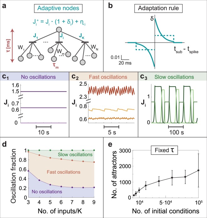
Figure 1.
Adaptive nodes in a feedforward network. (a) A schema of N input units connected with fixed weights (synapses), Wm, to K terminals (dendrites) which are connected with adaptive weights, Ji, to an output unit. Delays between input units and the output unit are denoted by τm and the dynamics of the output unit is governed by leaky integrated-and-fire neuron, eq. (1). After an adaptation step, is a function of its relative change, δ, and an additive noise, η, eq. (2). (b) A typical profile of δ = 0.05 * exp(−|Δ|/15) * sign(Δ) (solid blue line), where Δ measures the time-lag between a sub-threshold stimulation arriving from a terminal and another one which generates a spike. Δ is measured in ms. A simplified two-level adaptive rule (dashed blue line). Both adaptive rules have a cutoff at 50 ms. (c) Simulation results of (a) with K = 3 and N = 15, where inputs are stimulated simultaneously at 5 Hz. Three types of stationary solutions for Ji were found: (c1) Fixed values. (c2) Fast oscillations characterized by relatively small fluctuations around a fixed value. (c3) Slow oscillations characterized by large fluctuations and semi-flat periods at extreme values. (d) Fraction of the three types of stationary solutions in (c), as a function of N/K for K = 3, obtained in exhaustive search simulations (Methods). (e) Number of different stationary firing patterns, attractors, and their standard deviation, for K = 3 and N = 9 as a function of the number of different random initial conditions for Wm (Methods).

