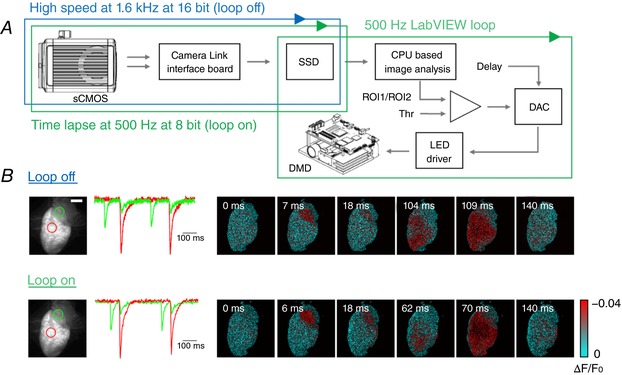
Figure 2. Real‐time optical intervention.

A, schematic workflow of the hardware and software architecture. A sCMOS camera, connected through two camera links to the workstation, saves the data in a RAID array of solid‐state disks (SSD). The camera can run either in high‐speed (blue cycle) or time‐lapse modality for closed‐loop operation (green cycle). During the latter, custom‐written LabVIEW software performs a real‐time analysis on images as they are saved on the SSD (green cycle): a previously acquired image of the heart is used as reference to select two ROIs, whose mean values are compared every 2 ms. When the ratio between the two ROIs exceeds the absolute value of a set threshold (Thr), optogenetic stimulation is activated, with user‐defined temporal delay and intensity. B, optical mapping during sinus rhythm with the two modalities: in loop‐off at a frame rate of 1.6 kHz (16‐bit images) and in loop‐on modality operating at 0.5 kHz (8‐bit images). The fluorescence signal (∆F/F 0) of two ROIs selected on atrium and ventricle (green and red circle respectively, reported on the fluorescence baseline image) are shown for both acquisition modalities. Scale bar: 2 mm.
