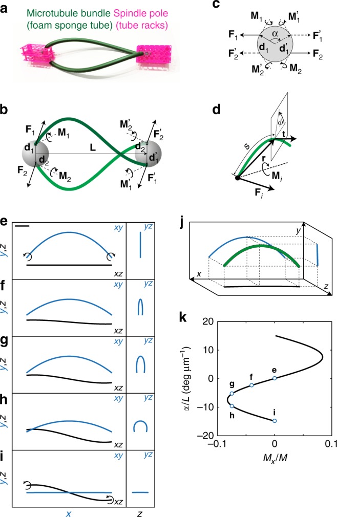
Fig. 3.

Theory for shapes of microtubule bundles. a Macroscopic model of the spindle constructed as an illustration of our physical model. b Scheme of the model. Microtubule bundles (green) extend between spindle poles (spheres) at the distance L. Straight arrows denote forces F1,2, and positions at the spheres d1,2, ; curved arrows denote torques . c View at the spindle pole along the spindle axis. The angle between the vectors d1 and is α; other symbols as in b. d Scheme of a bundle. Arrows depict contour length s, radial vector r, normalized tangent vector t, and torsion angle ϕ; other symbols as in b. e–i Predicted shapes of the bundles. Three projections: left, xy (blue), xz (black); right, yz (blue), see scheme in j. Parameters are: M1 = (0,0,180), (−5,−30,111), (−10,−70,115), (−10,−128,80), (0,−150,0) pNμm for e–i, respectively. j Scheme of the projections from e to i. k Twist of a microtubule bundle, α, divided by spindle length, L, as a function of the twisting moment, Mx = Mix, normalized to the bending moment, (the same curve for i = 1,2). Points denoted by letters e–i correspond to the shapes shown in respective panels. The other parameters are L = 12 μm, d = 1 μm, and κ = 900 pN μm2. Scale bars, 2 μm
