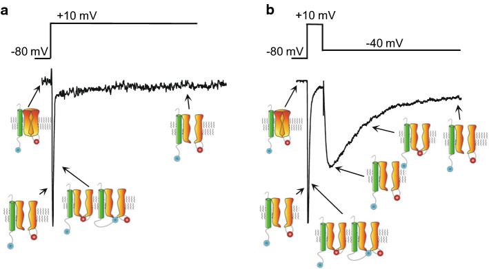
Fig. 2.
Three Nav current components, INaT, INaP, and INaR, resolved in steady-state voltage-clamp experiments. In the example voltage-clamp paradigm illustrated, INaT and INaP, are revealed during the depolarizing voltage step to + 10 mV (a), and INaR is observed on membrane repolarization (from + 10 mV) to − 40 mV (b). In both the left and right panels, the waveform of the evoked Nav currents is shown below the voltage-clamp paradigm, and schematics of Nav channel gating states are presented; the intrinsic channel inactivation gate is shown in red and the open-channel blocking particle is depicted in blue

