Fig. 3.
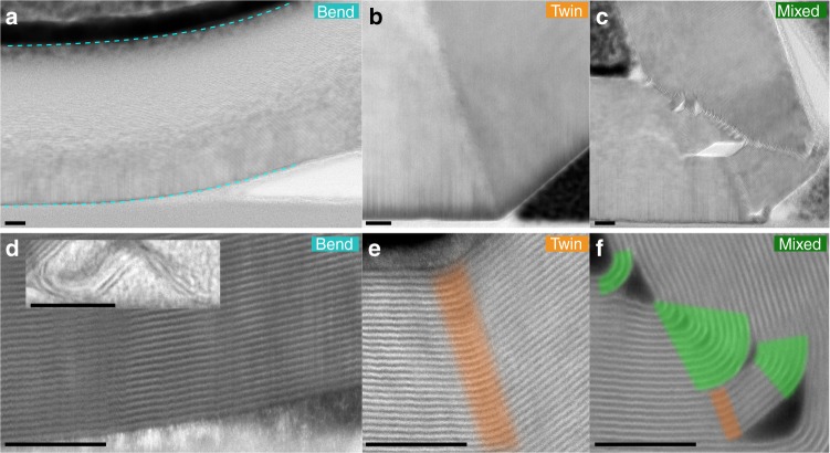
HAADF STEM images of different bending phenomena in graphite. a–c Bright field STEM images showing the microstructure of graphite for each bending mode: Bend, Twin and Mixed modes. The bend angle and number of basal planes in the crystal thickness for each are θ = 12°, N1 = 114 basal planes; θ = 40°, N1 = 559; and θ = 115°, N1 = 107, respectively. d–f HAADF STEM images demonstrating the different ways vdW crystals modify the arrangement of basal planes to accommodate strain induced by bending. The inset in d shows a 95° bend angle in a graphene bilayer. Areas of discrete twin boundaries are highlighted orange and areas of nanotube-like curvature are highlighted green. The mixed bending mode exhibits multiple discrete twins converging on a region of nanotube-like curvature and is only observed for the largest bend angles. All scale bars 5 nm

