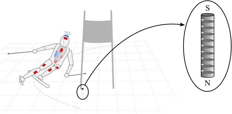
FIGURE 1.
Illustration of the experimental setup during a left turn. The inertial sensors are represented by the red boxes. The reference differential GNSS system is illustrated in blue with the antenna fixed to the helmet and the data logger worn on the back. The back protector contained the low-cost GNSS system with the antenna located approximately between the shoulder blades, as well as the data logger integrated in the inertial sensor fixed to the protector’s left side. The magnets were completely buried into the snow, close to the gate’s pole. A zoomed view of the buried magnet is provided on the right side of the illustration.

