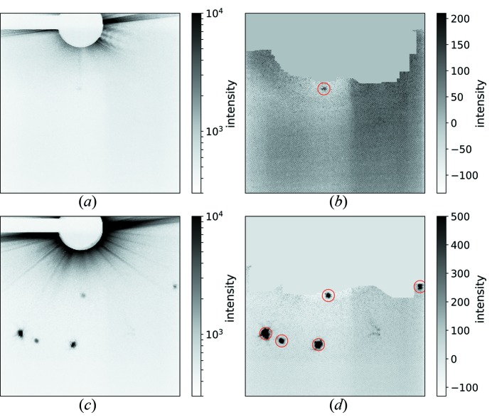
Figure 3.
Example diffraction patterns recorded with one pulse (a) and (b), and 20 pulses (c) and (d), each at a fluence of 0.5 ± 0.3 µJ µm−2. Panels (a) and (c) display the raw images on a logarithmic gray scale and (b) and (d) show the corrected images on a linear gray scale after background subtraction, masking of jet streak, and identification of the peaks. The peak locations are indicated by red circles. Panels (a) and (b) show a typical pattern with one very weak peak whereas (c) and (d) show a strong pattern with multiple peaks from different crystals recorded in the course of the pulse train. One peak from the 100 class of Bragg reflections and multiple peaks from the 110 class were found. Based on the angle between some of the 110-peaks and the beam center, these cannot originate from the same crystal lattice.

