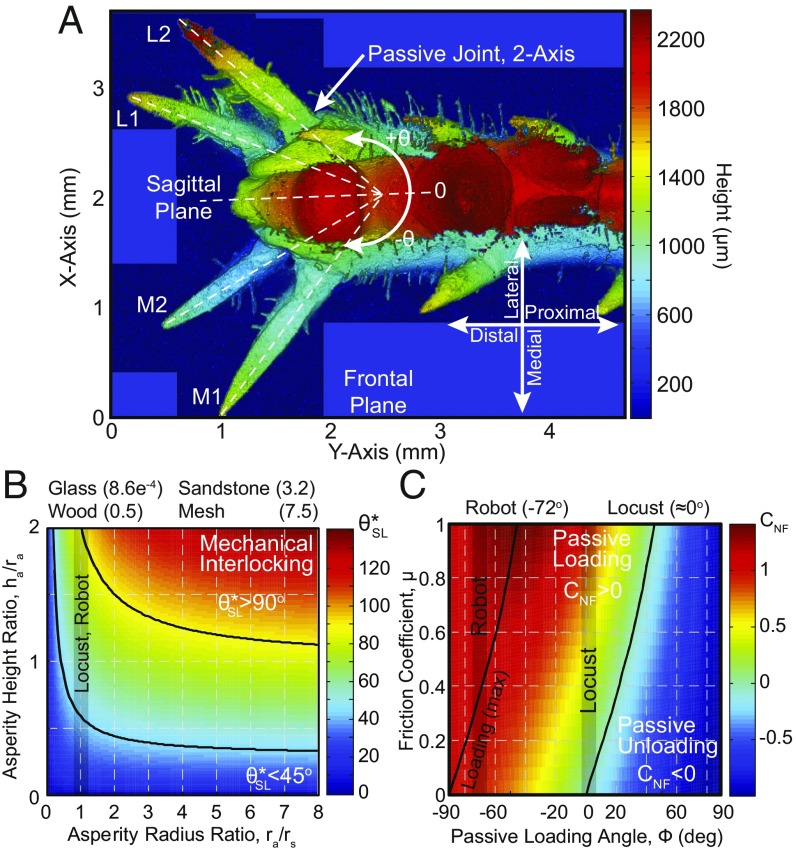
Fig. 5.
Locust friction mechanisms. (A) The locust’s foot with spines and adhesive pads (3D surface profilometer micrograph). The passive two-axis joint allows for nearly 180° in the sagittal plane and a difference of −10° in the frontal plane. (Magnification: 100.) (B) Spine-asperity interaction plot which determines the potential increases in the effective loading angle as a function of the spine tip radius, , asperity radius, , and asperity height, . The average asperity radius ratios, , of the tested materials are listed above the plot. (C) Adhesive pad interaction plot, which determines the passive loading coefficient, .

