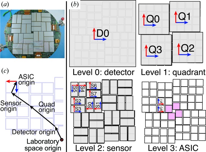
Figure 1.
Overview of the CSPAD (Cornell–SLAC Pixel Array Detector). (a) Photograph of the instrument (credit: Philip Hart). (b) Hierarchical organization. Each level groups objects that can be refined together. The pink ASICs in level 3 are used with powder patterns for quadrant alignment (§3.2). The blue and red vectors are the d x and d y directions used to orient the group. The d n vector completing the coordinate system is orthogonal to both, pointing out of the page for levels 0–2. At level 3, a y-axis sign flip is used to align the fast (blue) and slow (red) directions used to read out the pixels from the raw data, which also flips d n to point into the page (note the inverted ‘A0’ and ‘A1’ labels). (c) Origin vectors d n for each level of the CSPAD hierarchy. Starting at the origin of laboratory space, the detector is shifted by the detector origin vector. The deeper hierarchy levels point from the parent object origin to the child object origins, or in the case of the ASICs to the position of the (0, 0) pixel. Note that it might be expected that quadrants 1–3 would be rotated 90, 180 and 270° clockwise, respectively, and that S6 and S7 would be rotated 180°, all to maintain the fourfold symmetry of the detector. However, how the metrology is converted from optical measurements to vectors is arbitrary and varies each time the CSPAD is reassembled, sometimes producing a quadrant pattern without fourfold symmetry. Such is the case for the L785 experiment illustrated here. DIALS handles arbitrary configurations, so this is not an issue.

