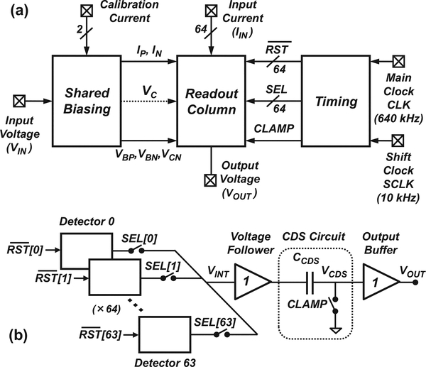
Fig. 1.
System-level diagram of the FSCV detector array. (a) The system consists of a read-out column along with on-chip biasing and timing blocks. (b) The read-out column contains 64 detectors that share a common output stage consisting of a correlated double sampling (CDS) circuit and an output buffer. Detectors are switched sequentially using time-division multiplexing.

