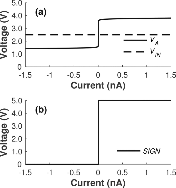
Fig. 8.
Simulation results illustrating the signals used to generate a binary output signal corresponding to the sign of the current. (a) The output of the regulation amplifier A1 in Fig. 2a, i.e., node VA, is pulled several hundred millivolts higher and lower than the applied voltage VIN for positive and negative input currents, respectively. (b) The two signals in (a) can be fed to the comparator in Fig. 9 to generate the desired binary output signal SIGN.

