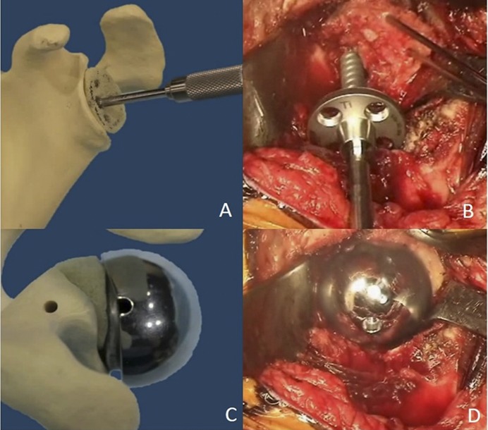
Fig. 1.
Figs. 1-A through 1-D Illustrative steps in graft placement and technique. Fig. 1-A A Sawbones graft (Pacific Research Laboratories) shaped to fit the defect with a tap inserted through the graft. Fig. 1-B Intraoperative image of a provisionally pinned humeral head autograft with a screw-in baseplate being inserted to compress the graft into the defect. Fig. 1-C Uncontained defect with a hooded glenosphere oriented to make contact with the graft and load-share with the baseplate. Fig. 1-D Intraoperative image after completed grafting of an uncontained defect and glenosphere contact with the posterior part of the graft.

