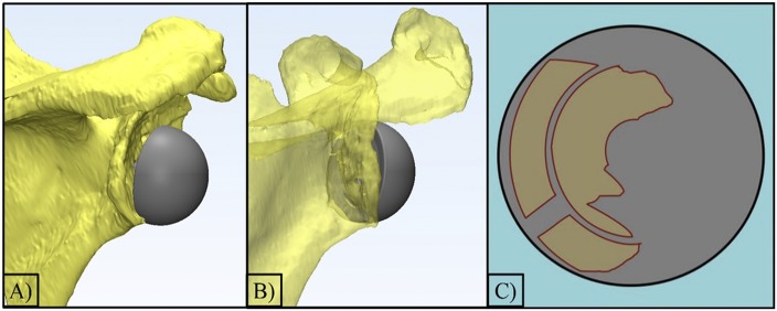
Fig. 5.
Figs. 5-A, 5-B, and 5-C An example of the software program, 3-matic (Materialise), that was used to calculate the contact area of the implant (baseplate and glenosphere) that intersected with the host bone. Fig. 5-A The final positioning of the implant on the scapula with a gap between the glenosphere and the host bone. Fig. 5-B The translucent model displays the anterior host bone contact. Fig. 5-C A 2D representation of the intersecting area between the host bone and the baseplate.

