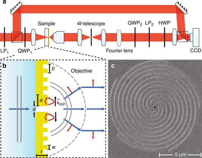
Fig. 2. Schematic view of the setup and plasmonic spiral antenna.
a Combined Fourier polarimetry and holography setup, consisting of a transmission microscope, two polarimeters and a reference beam. The microscope contains a 4f-telescope for spatial filtering of light from a single antenna. b Principle of plasmonic bullseye/spiral nanostructure. Light impinging from the glass side excites the single hole in a thick metal film. SPPs launched by the hole at the air side scatter out at the spiral corrugation. The red arrows denote the directions of the SPP and free-space electric fields. c SEM micrograph of a m = −5 spiral antenna

