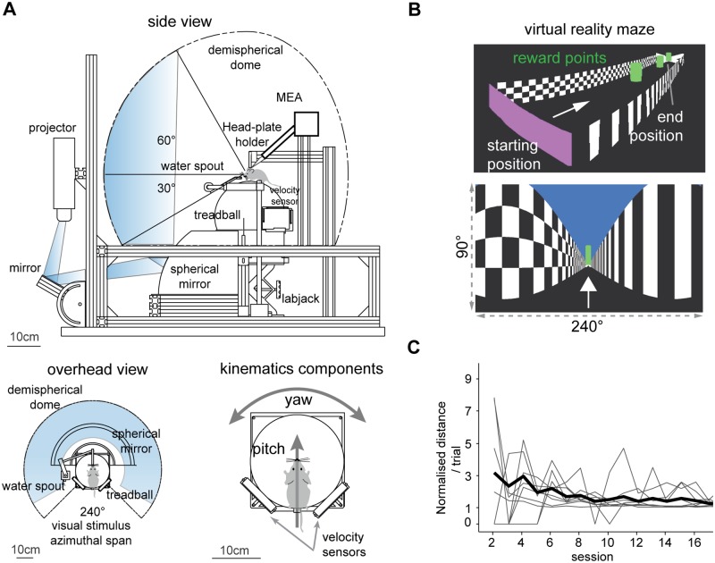
Fig 1. Virtual reality apparatus.
(A) Schematic view of the virtual reality system with approximate image path of the visual stimulus from the projector to the demi-spherical screen. Bottom left. Overhead view of the coverage of the mouse visual field. Bottom right. Mouse on the spherical treadmill, or treadball. The signals from the velocity sensors are integrated to determine translation (pitch) and heading (yaw) movements of the mouse in the virtual environment. Mouse drawings not to scale. (B) Virtual reality environment. Top, perspective view of the virtual corridor. Bottom, subject perspective of the VR maze with horizontal and vertical span of the virtual camera. (C) Mean normalised distance ran per trial in first 16 days. Gray lines are subjects, thick black line is average for all trained mice (n = 10).

