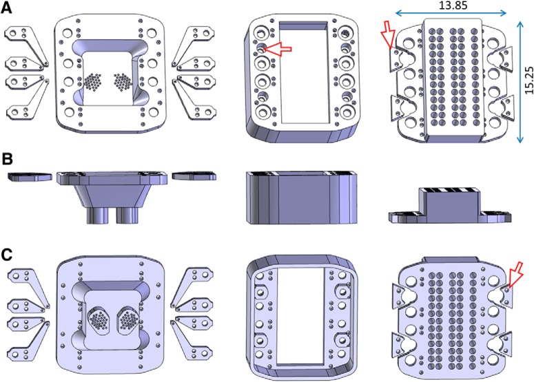
Figure 2.
Designing the microdrive. A, Top view of the pieces, from left to right: left shuttles, bottom part, right shuttles, middle part, and lid. The red arrowhead points to the annulus (inside the socket for the ferrule) that avoids the ferrule being pressed into body of the microdrive. Main dimensions are indicated in millimeters. B, Occipital view of the same pieces as in A, in the same order. C, Bottom view of the same pieces as in A, in the same order. The arrowhead points to the locking piece that slides into the diced groove of the ferrule and is locked in position by two insect pins to avoid the ferrule being torn out when the mating sleeves are pulled off to disconnect the animal from the laser.

