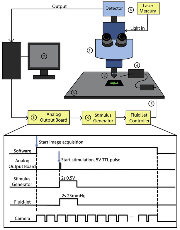
FIGURE 3. Imaging setup for calcium imaging and hair-cell stimulation.
Schematic of the imaging system requirements outlined in Section 2.1. (1) upright microscope; (2) water immersion objective; (3) fixed stage; (4) manipulator to position stimulation pipette; (5) fluid jet (and controller) to stimulate hair cells; (6) light source and detector; (7) imaging software; (8) analog output board; (9) stimulus generator. The bottom panel outlines the signals used to coordinate imaging with hair-cell stimulation. The software starts the image acquisition. This triggers the camera to capture at a given frame rate. During the time series to start hair-cell stimulation, a 5 V TTL pulse is sent from the software at a defined frame rate to the stimulus generator using an analog output board. The stimulus generator converts the TTL pulse into an analog voltage signal with a defined duration and magnitude that is then sent to the fluid jet controller. The fluid jet controller converts the voltage signal into fluid flow by applying positive or negative pressure on the fluid within the stimulating pipette. This, in turn, deflects hair bundles and activates hair cells.

