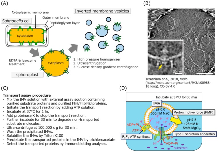
Figure 2.
Schematic drawing of the typical in vitro protein transport assay. (A) Schematic drawing of the IMV preparation. The cultivated cells were converted to spheroplasts by treatment with EDTA and lysozyme to remove the outer membrane and the peptidoglycan layer, respectively, then disrupted by a high pressure homogenizer to form the inside-out vesicles. The vesicles were purified by ultracentrifugation and sucrose density gradient centrifugation. (B) Electron cryotomographic image of the typical IMV in which the flagellar basal structure is embedded. The lower left panel is an enlarged image of the basal body in the IMV. The disk like density formed by FlhA cytoplasmic domain is indicated by yellow arrow. This image was cited from Terashima et al. In Vitro Reconstitution of Functional Type III Protein Export and Insights into Flagellar Assembly. MBio. 9, e00988–18. (2018) [25]. Please read the full license for further details at—https://creativecommons.org/licenses/by/4.0/. (C) (D) The in vitro Type III protein transport assay method. (C) The procedures for the in vitro transport assay was described as a list. (D) To apply the initial PMF to the IMV, the IMVs filled with 300 mM Na+ solution at pH 6.0 were suspended in solution at pH 7.5 containing 125 mM K+ and 5 mM MgCl2. The inverted membrane vesicle is mixed with the export substrates, ATP-Mg2+, the FliH2/FliI complex and/or FliJ depending on experiment purpose. Addition of ATP induces proton pumping into the IMVs by reverse reaction of the endogenous FoF1-ATP synthase, resulting in generating PMF across the membrane. The PMF and ATP hydrolysis drive the protein transport into the IMV. The transported proteins are detected by immunoblotting.

